Asus T3-P5G43 User Manual
Browse online or download User Manual for Computers Asus T3-P5G43. Asus T3-P5G43 User Manual
- Page / 104
- Table of contents
- BOOKMARKS
Rated. / 5. Based on customer reviews
T-P5G43
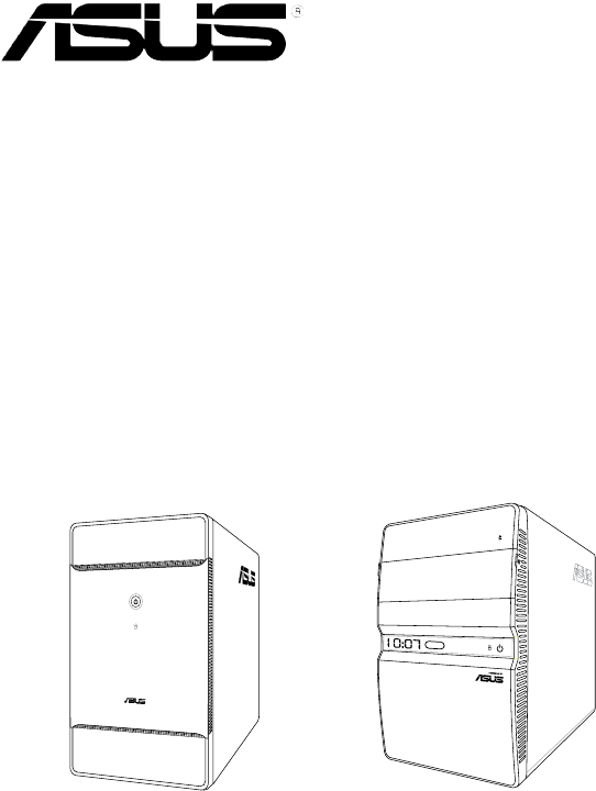
ASUS PC (Desktop Barebone)
* Only some of the T4 models have the
Time and IR LED display.
T3-P5G43 T4-P5G43*
- ASUS PC (Desktop Barebone) 1
- First Edition 2
- November 2008 2
- Contents 3
- Safety information 7
- About this guide 8
- Wheretondmoreinformation 9
- System package contents 10
- System introduction 11
- 1.1 Welcome! 12
- 1.2 Front panel 12
- 1.2.2 T4-P5G43 front panel 14
- 1.3 Rear panel 16
- 1-7ASUS T-P5G43 17
- 1.4 Internal components 18
- 1-9ASUS T-P5G43 19
- Basic installation 21
- Standy Power Powered Off 22
- P5Q18L Onboard LED 22
- 2.3 Removing the cover 23
- 2.4 Power supply unit 24
- P5Q18L CPU socket 775 25
- P5Q18L CPU fan connector 27
- 2.6 Installing a DIMM 28
- 2-9ASUS T-P5G43 29
- 2.6.2 DIMM installation 32
- 2.7.1 Expansion slots 33
- 2-15ASUS T-P5G43 35
- Voltage selector 37
- 2.11 Replacing the cover 38
- Starting up 39
- 3.2 Powering up 40
- 3.3 Support CD information 41
- 3.3.2 Drivers menu 42
- 3.3.3 Utilities menu 43
- ASUS Update 44
- FarStone Utility 44
- 3.4 Software information 45
- The First Screen 46
- The Express Gate Environment 46
- UsingtheCongurationPanel 48
- Using the LaunchBar 49
- 3-12 Chapter 3: Starting up 50
- 3-13ASUS T-P5G43 51
- Using the Photo Manager 52
- Using the Online Games 52
- Updating Express Gate 53
- Repairing Express Gate 53
- 3-16 Chapter 3: Starting up 54
- Motherboard info 55
- 4.1 Introduction 56
- 4.2 Motherboard layout 56
- 4.3 Jumpers 57
- P5Q18L CPU Fan Switch 58
- 4.4 Connectors 59
- P5Q18L IDE connector 60
- P5Q18L SATA connectors (ICH10 61
- SPDIF_OUT 62
- BIOS setup 63
- Vista environment 64
- 5.1.3 AFUDOS utility 66
- UpdatingtheBIOSle 67
- 5.1.5 ASUS Update utility 70
- 5-9ASUS T-P5G43 71
- T-P5G43.ROM 72
- 5.2 BIOS setup program 73
- 5.2.1 BIOS menu screen 74
- 5.2.2 Menu bar 74
- 5.2.3 Navigation keys 74
- 5-13ASUS T-P5G43 75
- 5.3 Main menu 76
- Type [Auto] 77
- LBA/Large Mode [Auto] 77
- 5.3.4 CongureSATAas[IDE] 78
- 5.3.5 System Information 79
- 5.4 Advanced menu 80
- 5.4.2 Chipset 82
- Front Panel Type [HD Audio] 83
- PAVP Mode [Disabled] 83
- DVMT /FIXED Memory [256MB] 83
- 5.4.4 USBConguration 84
- USB 2.0 Controller [Enabled] 85
- BIOS EHCI Hand-Off [Enabled] 85
- Legacy USB Support [Auto] 85
- 5.5 Power menu 86
- 5.5.5 APMConguration 87
- 5-26 Chapter 5: BIOS setup 88
- 5.5.6 Hardware Monitor 89
- 5.6 Boot menu 90
- 5-29ASUS T-P5G43 91
- 5.6.3 Security 92
- Change User Password 93
- Clear User Password 93
- Password Check [Setup] 93
- 5.7 Tools menu 94
- 5.7.2 Express Gate 95
- LED Poster Backlight 96
- 5.8 Exit menu 97
- 5-36 Chapter 5: BIOS setup 98
- Appendix 99
- A.2 Dubug code table 100
- (continued on the next page) 101
- XP installation 103
- A-6 Appendix 104
Summary of Contents
Page 1 - ASUS PC (Desktop Barebone)
T-P5G43ASUS PC (Desktop Barebone) * Only some of the T4 models have the Time and IR LED display. T3-P5G43 T4-P5G43*
Page 2 - November 2008
xSystem package contentsCheck your T-P5G43 system package for the following items.If any of the items is damaged or missing, contact your retailer imm
Page 3 - Contents
A-2 AppendixA.1 PowersupplyspecicationsOutput characteristicsOutput voltageLoad range Surge <10msRegulation Ripple and noiseMin Max (%) Vpp Vpp
Page 4
A-3ASUS T-P5P43A.3 Using the Remote Control (optional)Use the remote control to launch the Media Center program to play media les such as music and
Page 5
A-4 AppendixNo. Button Description4. Fast-foward Press to fast-forward a media le.5. Next track Press to go to the next track.6. InformationPress to
Page 6
A-5ASUS T-P5P43A.4 Integrating AHCI driver to Windows® XP installationnLite allows you to integrate the AHCI driver into the Windows® XP installati
Page 7 - Safety information
A-6 Appendix7. Click Insert > Multiple driver folder to select the AHCI folder, then click OK. Select the driver path and click OK. Select Intel(R
Page 8 - About this guide
T3-P5G43 T4-P5G43*Chapter 1System introductionThis chapter gives a general description of ASUS T-P5G43. The chapter lists the system features includi
Page 9 - Wheretondmoreinformation
1-2 Chapter 1: System introduction1.1 Welcome!Thank you for buying an ASUS T-P5G43!ASUS T-P5G43 is an all-in-one barebone system with a versatile hom
Page 10 - System package contents
1-3ASUS T-P5G431. Drive door. Open this door to access the optical drive.2. Power button . Press this button to turn the system on/off.3. HDD LED
Page 11 - System introduction
1-4 Chapter 1: System introduction1.2.2 T4-P5G43 front panel21645External1. Drive door. Open this door to access the optical drive.2. Front panel I
Page 12 - 1.2 Front panel
1-5ASUS T-P5G437. USB 2.0 ports 2.0. These Universal Serial Bus 2.0 (USB 2.0) ports are available for connecting USB 2.0 devices such as a mouse, pri
Page 13
1-6 Chapter 1: System introduction1.3 Rear panelThe system rear panel includes the power connector and several I/O ports that allow convenient connec
Page 14 - 1.2.2 T4-P5G43 front panel
1-7ASUS T-P5G4322. External SATA port. This port connects to an external Serial ATA hard disk drive.DO NOT insert different connectors into the exter
Page 15
1-8 Chapter 1: System introduction1.4 Internal componentsThe illustration below is the internal view of the system when you remove the top cover and
Page 16 - 1.3 Rear panel
1-9ASUS T-P5G431. ASUS motherboard2. LGA775 socket with PnP cap3. DIMM sockets for DDR24. Serial ATA connectors5. PCI Express™ x16 slot for discr
Page 17 - 1-7ASUS T-P5G43
iiCopyright © 2008 ASUSTeK Computer Inc. All Rights Reserved.No part of this manual, including the products and software described in it, may be repro
Page 18 - 1.4 Internal components
1-10 Chapter 1: System introduction
Page 19 - 1-9ASUS T-P5G43
T3-P5G43 T4-P5G43*Chapter 2This chapter provides step-by-step instructions on how to install components in the system.Basic installation* Only some
Page 20
2-2 Chapter 2: Basic installation2.1 PreparationBefore you proceed, ensure that you have all the components you plan to install in the system.Basic c
Page 21 - Basic installation
2-3ASUS T-P5G433. Slightly pull the cover toward the rear panel until the side tabs are disengaged from the chassis.4. Lift the cover, then set asid
Page 22 - P5Q18L Onboard LED
2-4 Chapter 2: Basic installation2.4 Power supply unitYou need to turn over the power supply unit (PSU) section on the side before you can install a
Page 23 - 2.3 Removing the cover
2-5ASUS T-P5G432.5 CPU installation• Your boxed Intel® LGA775 processor package should come with installation instructions for the CPU, heatsink, an
Page 24 - 2.4 Power supply unit
2-6 Chapter 2: Basic installation3. Lift the load lever in the direction of the arrow to a 135º angle.4. Lift the load plate with your thumb and for
Page 25 - P5Q18L CPU socket 775
2-7ASUS T-P5G432.5.2 Installing CPU fan and heatsink assemblyThe Intel® LGA775 processor requires a specially designed heatsink and fan assembly to e
Page 26
2-8 Chapter 2: Basic installation2.6 Installing a DIMMThe system motherboard comes with two Double Data Rate 2 (DDR2) Dual Inline Memory Module (DIMM
Page 27 - P5Q18L CPU fan connector
2-9ASUS T-P5G43Vendor Part No. Size Chip No. C/L BrandDIMM supportA* B*Apacer 78.A1G9O.9K4 2GB DS AM4B5808CQJS7E N/A APACER • •CORSAIR VS1GB667D2 1GB
Page 28 - 2.6 Installing a DIMM
iiiContentsNotices ... viSafety information ...
Page 29 - 2-9ASUS T-P5G43
2-10 Chapter 2: Basic installationDDR2(800MHz)QualiedVendorsListVendor Part No. SizeSS/ DSChip No. C/L BrandDIMM supportA* B*A-DATA M2OAD6H3J417
Page 30
2-11ASUS T-P5G43DDR2(800MHz)QualiedVendorsListVendor Part No. SizeSS/ DSChip No. C/L BrandDIMM supportA* B*Qimonda HYS64T256020EU-25F-C2 2GB DS
Page 31
2-12 Chapter 2: Basic installation2.6.2 DIMM installationTo install a DDR2 DIMM:1. Locate the two DIMM sockets on the motherboard.2. Unlock a socke
Page 32 - 2.6.2 DIMM installation
2-13ASUS T-P5G432.7 Installing an expansion cardIn the future, you may need to install expansion cards. The motherboard has one PCI and one PCI Expre
Page 33 - 2.7.1 Expansion slots
2-14 Chapter 2: Basic installation2.7.2 Expansion card installationTo install an expansion card:1. Before installing the expansion card, read the do
Page 34
2-15ASUS T-P5G43When using a PCI card on shared slots, ensure that the drivers support “Share IRQ” or that the cards do not need IRQ assignments. Othe
Page 35 - 2-15ASUS T-P5G43
2-16 Chapter 2: Basic installation2.9 Installing a Serial ATA disk driveThe system supports one Serial ATA hard disk drive.To install a Serial ATA ha
Page 36
2-17ASUS T-P5G432.10 Replacing the power supply unitReplace the power supply unit (PSU) after installing the system components and reconnecting the c
Page 37 - Voltage selector
2-18 Chapter 2: Basic installation2.11 Replacing the coverTo replace the cover:1. Turn the chassis upright.2. Position the front edge of the cover
Page 38 - 2.11 Replacing the cover
T3-P5G43 T4-P5G43*Chapter 3Starting upThis chapter helps you power up the system and install drivers and utilities from the support CD.* Only some of
Page 39 - Starting up
ivContents3.3.1 Running the support CD ... 3-33.3.2 Drivers menu ...
Page 40 - 3.2 Powering up
3-2 Chapter 3: Starting up3.1 Installing an operating systemThe barebone system supports Windows® 32-bit XP / 32-bit Vista / 64-bit XP / 64-bit Vista
Page 41 - 3.3 Support CD information
3-3ASUS T-P5G433.3.1 Running the support CDTo begin using the support CD, place the CD in your optical drive. The CD automatically displays the Drive
Page 42 - 3.3.2 Drivers menu
3-4 Chapter 3: Starting up3.3.2 Drivers menuThe drivers menu shows the available device drivers if the system detects installed devices. Install the
Page 43 - 3.3.3 Utilities menu
3-5ASUS T-P5G433.3.3 Utilities menuThe Utilities menu shows the applications and other software that the motherboard supports. ASUS InstAll - Install
Page 44 - FarStone Utility
3-6 Chapter 3: Starting up3.3.4 ASUS contact informationThe Contact tab displays the ASUS contact information.ASUS UpdateInstalls the ASUS Update tha
Page 45 - 3.4 Software information
3-7ASUS T-P5G43ASUS Express GateASUS Express Gate is an instant-on environment that gives you quick access to the Internet. Within a few seconds
Page 46 - The Express Gate Environment
3-8 Chapter 3: Starting upThe First ScreenExpress Gate’s rst screen appears within a few seconds after you power on the computer. From here, y
Page 47
3-9ASUS T-P5G43Knowing the Express Gate hot-keysHere is a list of common-used hot-keys for Express Gate.In the First Screen:Key FunctionPAUSE/BREAK Po
Page 48 - UsingtheCongurationPanel
3-10 Chapter 3: Starting upUsingtheCongurationPanelUse the conguration panel to change various Express Gate settings.• Screen Settings: Choose t
Page 49 - Using the LaunchBar
3-11ASUS T-P5G43Using the LaunchBarThe LaunchBar has several system icons that show you various system statuses and let you congure individual Expres
Page 50 - 3-12 Chapter 3: Starting up
vContents5.4 Advanced menu ... 5-185.4.1 CPU Conguration ...
Page 51 - 3-13ASUS T-P5G43
3-12 Chapter 3: Starting upNetworkPower offEnter OSCancel and return to Express Gate RestartCheck to save userproleOpenCongurationPanel Click to
Page 52 - Using the Online Games
3-13ASUS T-P5G433. Makethepropernetworkcongurations.Each network interface is enabled immediately when you check the box next to it.• If you us
Page 53 - Repairing Express Gate
3-14 Chapter 3: Starting upUsing the Photo ManagerExpress Gate provides a easy-to-use Photo Manager that allows you to view pictures stored in your h
Page 54 - 3-16 Chapter 3: Starting up
3-15ASUS T-P5G43ConguringExpressGateinBIOSSetupEnter BIOS setup by pressing DEL key after powering on or by clicking on the BIOS setup icon on E
Page 55 - Motherboard info
3-16 Chapter 3: Starting up
Page 56 - 4.2 Motherboard layout
4-1T3-P5G43 T4-P5G43*Chapter 4Motherboard infoThis chapter gives information about the motherboard that comes with the system. This chapter includes
Page 57 - 4.3 Jumpers
4-2 Chapter 4: Motherboard Info4.1 IntroductionThe motherboard comes already installed in ASUS T-P5G43 system. This chapter provides technical infor
Page 58 - P5Q18L CPU Fan Switch
4-3ASUS T-P5G434.3 Jumpers1. Clear RTC RAM (CLRTC)This jumper allows you to clear the Real Time Clock (RTC) RAM in CMOS. You can clear the CMOS memo
Page 59 - 4.4 Connectors
4-4 Chapter 4: Motherboard Info2. Keyboard/Mouse power (3-pin USB_KBMS_PW)This jumper allows you to enable or disable the keyboard / mouse wake-up a
Page 60 - P5Q18L IDE connector
4-5ASUS T-P5G434.4 ConnectorsThis section describes and illustrates the connectors on the motherboard.1. CPU fan connector (4-pin CPU_FAN)The fan co
Page 61 - P5Q18L SATA connectors (ICH10
viNoticesFederal Communications Commission StatementThis device complies with Part 15 of the FCC Rules. Operation is subject to the following two cond
Page 62 - SPDIF_OUT
4-6 Chapter 4: Motherboard Info3. IDE connector (40-1 pin PRI_IDE)This connector is for an IDE 100/66 signal cable, a blue connector for the primary
Page 63 - BIOS setup
4-7ASUS T-P5G434. Serial ATA connectors (7-pin SATA1, SATA2, SATA3)These connectors are for the Serial ATA signal cables for Serial ATA hard disk dri
Page 64 - Vista environment
4-8 Chapter 4: Motherboard Info5. Optical drive audio connector (4-pin CD)These connectors allow you to receive stereo audio input from sound source
Page 65
5-1T3-P5G43 T4-P5G43*Chapter 5BIOS setupThis chapter tells how to change system settings through the BIOS Setup menus and describes the BIOS paramete
Page 66 - 5.1.3 AFUDOS utility
5-2 Chapter 5: BIOS setup5.1 Managing and updating your BIOSThe following utilities allow you to manage and update the motherboard Basic Input/Output
Page 67 - UpdatingtheBIOSle
5-3ASUS T-P5G43To update the BIOS using EZ Flash 2:1. Visit the ASUS website (www.asus.com) to download the latest BIOS le for the motherboard.2. S
Page 68
5-4 Chapter 5: BIOS setup5.1.3 AFUDOS utilityThe AFUDOS utility allows you to update the BIOS le in DOS environment using a bootable oppy disk with
Page 69
5-5ASUS T-P5G43UpdatingtheBIOSleTo update the BIOS le using the AFUDOS utility:1. Visit the ASUS website (www.asus.com) and download the latest
Page 70 - 5.1.5 ASUS Update utility
5-6 Chapter 5: BIOS setup5.1.4 ASUS CrashFree BIOS 3 utilityThe ASUS CrashFree BIOS 3 is an auto recovery tool that allows you to restore the BIOS l
Page 71 - 5-9ASUS T-P5G43
5-7ASUS T-P5G43Recovering the BIOS from the support CDTo recover the BIOS from the support CD:1. Remove any oppy disk from the oppy disk drive, the
Page 72 - T-P5G43.ROM
viiSafety informationElectrical safety• To prevent electrical shock hazard, disconnect the power cable from the electrical outlet before relocating th
Page 73 - 5.2 BIOS setup program
5-8 Chapter 5: BIOS setupInstalling ASUS UpdateTo install ASUS Update:1. Place the support CD in the optical drive. The Drivers menu appears. 2. Cli
Page 74 - 5.2.3 Navigation keys
5-9ASUS T-P5G433. Select the ASUS FTP site nearest you to avoid network trafc, or click Auto Select. Click Next.Updating the BIOS through the Intern
Page 75 - 5-13ASUS T-P5G43
5-10 Chapter 5: BIOS setupUpdatingtheBIOSthroughaBIOSleTo update the BIOS through a BIOS le:1. Launch the ASUS Update utility from the Window
Page 76 - 5.3 Main menu
5-11ASUS T-P5G435.2 BIOS setup programThis motherboard supports a programmable rmware chip that you can update using the provided utility described
Page 77 - LBA/Large Mode [Auto]
5-12 Chapter 5: BIOS setup5.2.1 BIOS menu screen• The BIOS setup screens shown in this chapter are for reference purposes only, and may not exactly
Page 78 - 5.3.4 CongureSATAas[IDE]
5-13ASUS T-P5G435.2.4 Menu itemsThe highlighted item on the menu bar displays the specic items for that menu. For example, selecting Main shows the
Page 79 - 5.3.5 System Information
5-14 Chapter 5: BIOS setup5.3 Main menuWhen you enter the BIOS Setup program, the Main menu screen appears, giving you an overview of the basic syste
Page 80 - 5.4 Advanced menu
5-15ASUS T-P5G435.3.3 SATA1, SATA2, SATA3, and SATA4While entering Setup, the BIOS automatically detects the presence of SATA devices. There is a sep
Page 81
5-16 Chapter 5: BIOS setupPIO Mode [Auto]Selects the PIO mode. Conguration options: [Auto] [0] [1] [2] [3] [4]DMA Mode [Auto]Selects the DMA mode. Co
Page 82 - 5.4.2 Chipset
5-17ASUS T-P5G435.3.5 System InformationThis menu gives you an overview of the general system specications. The BIOS automatically detects the items
Page 83 - DVMT /FIXED Memory [256MB]
viiiAbout this guideAudienceThis guide provides general information and installation instructions about ASUS T-P5G43 barebone system. This guide is in
Page 84 - 5.4.4 USBConguration
5-18 Chapter 5: BIOS setup5.4 Advanced menuThe Advanced menu items allow you to change the settings for the CPU and other system devices.Take caution
Page 85 - Legacy USB Support [Auto]
5-19ASUS T-P5G43CPU Ratio Setting [Auto]Allows you to adjust the ratio between the CPU Core Clock and the FSB Frequency. Conguration options: [Auto]
Page 86 - 5.5 Power menu
5-20 Chapter 5: BIOS setup5.4.2 ChipsetThe Chipset menu allows you to change the advanced chipset settings. Select an item then press <Enter> t
Page 87 - 5.5.5 APMConguration
5-21ASUS T-P5G435.4.3 OnboardDevicesCongurationOnboard Devices CongurationHigh Denition Audio [Enabled] Front Panel Type [HD Audio] SPDIF_OU
Page 88 - 5-26 Chapter 5: BIOS setup
5-22 Chapter 5: BIOS setupUSB Function [Enabled]Allows you to select the USB function. Conguration options: [Disabled] [Enabled] The USB Devices Enab
Page 89 - 5.5.6 Hardware Monitor
5-23ASUS T-P5G43USB 2.0 Controller [Enabled]Enables or disables the USB 2.0 Controller. Conguration options: [Disabled] [Enabled]The USB 2.0 Controll
Page 90 - 5.6 Boot menu
5-24 Chapter 5: BIOS setup5.5 Power menuThe Power menu items allow you to change the settings for the Advanced Conguration and Power Interface (ACPI
Page 91 - 5-29ASUS T-P5G43
5-25ASUS T-P5G435.5.5 APMCongurationAPM CongurationRestore on AC Power Loss [Power Off]Power On By RTC Alarm [Disabled]Power On By PCI Devices
Page 92 - 5.6.3 Security
5-26 Chapter 5: BIOS setupPower On By PCIE Devices [Disabled]When set to [Enabled], this parameter allows you to turn on the system through a PCI Expr
Page 93 - Password Check [Setup]
5-27ASUS T-P5G435.5.6 Hardware MonitorHardware MonitorCPU Temperature [45ºC/113ºF]MB Temperature [41ºC/105.5ºF]CPU Fan Speed [1190RPM]Smart Q-Fan
Page 94 - 5.7 Tools menu
ixConventions used in this guideWARNING: Information to prevent injury to yourself when trying to complete a task. CAUTION: Information to prevent dam
Page 95 - 5.7.2 Express Gate
5-28 Chapter 5: BIOS setup5.6 Boot menuThe Boot menu items allow you to change the system boot options. Select an item then press <Enter> to di
Page 96 - LED Poster Backlight
5-29ASUS T-P5G435.6.2 BootSettingsConguration Select Screen Select Item+- Change OptionF1 General HelpF10 Save and ExitESC ExitBoot
Page 97 - 5.8 Exit menu
5-30 Chapter 5: BIOS setupIf you forget your BIOS password, you can clear clear it by erasing the CMOS Real Time Clock (RTC) RAM. See section “4.3 Ju
Page 98 - 5-36 Chapter 5: BIOS setup
5-31ASUS T-P5G43User Access Level [Full Access]This item allows you to select the access restriction to the Setup items. Conguration options: [No Acc
Page 99 - Appendix
5-32 Chapter 5: BIOS setup5.7 Tools menuASUS EZ Flash 2Express Gate [Enabled] Enter OS Timer [10 Seconds] Reset User Data [No] LED POSTER CONFI
Page 100 - A.2 Dubug code table
5-33ASUS T-P5G435.7.2 Express GateAllows you to enable or disable the ASUS Express Gate feature. The ASUS Express Gate feature is a unique instant-on
Page 101 - (continued on the next page)
5-34 Chapter 5: BIOS setupThe following items appear only in some models with LED Display features. 5.7.3 LEDPosterCongurationTurn On/Off LED Time
Page 102
5-35ASUS T-P5G43Exit & Discard ChangesSelect this option only if you do not want to save the changes that you made to the Setup program. If you m
Page 103 - XP installation
5-36 Chapter 5: BIOS setup
Page 104 - A-6 Appendix
A-1T3-P5P43 T4-P5P43*AppendixAppendixThe Appendix includes the power supply unit specication, remote control for this system, as well as the integra
Related products and manuals for Computers Asus T3-P5G43
Computers Asus CG8265 User Manual

 (210 pages)
(210 pages)
Computers Asus Eee Pad MeMO 171 User Manual
(26 pages)
(26 pages)
Computers Asus P4-P5N9300 User Manual
(82 pages)
(82 pages)
Computers Asus S2-P8H61E User Manual
(80 pages)
(80 pages)
Computers Asus P1-P5945GCX User Manual


 (80 pages)
(80 pages)
Computers Asus P6-P7H55E User Manual
(67 pages)
(67 pages)
Computers Asus Essentio ES5000 User Manual
(174 pages)
(174 pages)
Computers Asus P2-P5945GCX User Manual
(56 pages)
(56 pages)
Computers Asus S1-AT5NM10E User Manual
(68 pages)
(68 pages)
Computers Asus Essentio CG8250 User Manual
(239 pages)
(239 pages)
Computers Asus Essentio CM1730 User Manual
(198 pages)
(198 pages)
Computers Asus CM1740 User Manual
(198 pages)
(198 pages)
Computers Asus T3-P5G965 User Manual
(80 pages)
(80 pages)
Computers Asus Essentio CM6730 User Manual
(198 pages)
(198 pages)
Computers Asus A7V266-EX User Manual
(116 pages)
(116 pages)
Computers Asus AE1 User Manual
(8 pages)
(8 pages)
Computers Asus TS300-E5 User Manual
(218 pages)
(218 pages)
Computers Asus Motherboard M2S-X User Manual
(86 pages)
(86 pages)
© 2020, manymanuals.com. All rights reserved. | 4.069 s |
 Manymanuals.com
 Manymanuals.de
 Manymanuals.fr
 Manymanuals.it
 Manymanuals.pl
 Manymanuals.cz
 Manymanuals.es
 Manymanuals-pt.com
Comments to this Manuals