Asus 1U User Manual
Browse online or download User Manual for PC/workstation barebones Asus 1U. ASUS 1U User's Manual
- Page / 34
- Table of contents
- BOOKMARKS
- R10-A2P4 1
- First edition V1 2
- July 2004 2
- Contents 3
- Safety information 5
- About this guide 6
- Product introduction 7
- 1.1 System package contents 8
- 1.3 Rear panel features 9
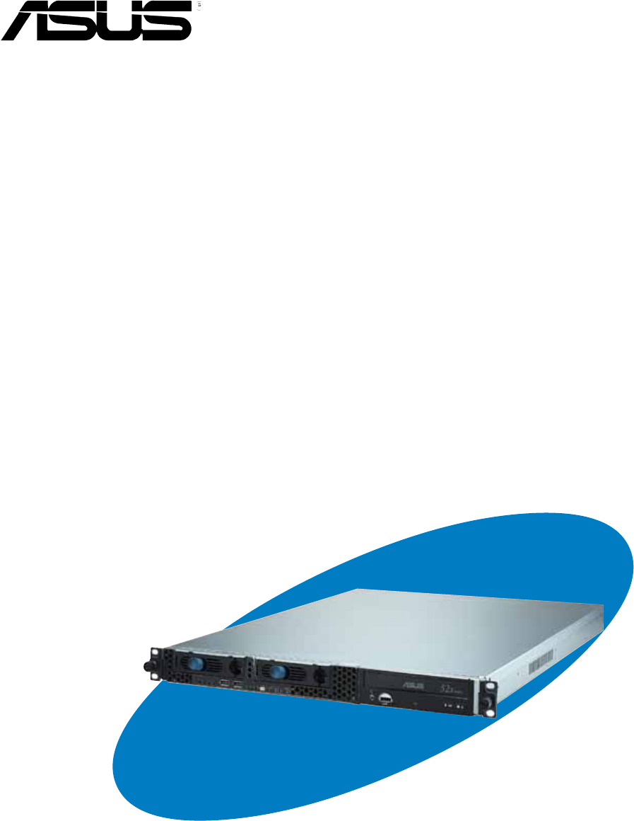
- 1.2 Front panel features 9
- 1.4 Internal features 10
- 1.5 LED information 11
- Hardware setup 13
- 2.1 Preparation 14
- 2.2.1 Removing the cover 15
- 2.2.2 Installing the cover 16
- 2.3 Motherboard installation 17
- CPU sockets 19
- 2.4 Hard disk drives 21
- SATA interface 22
- 2.5 Expansion slot 23
- 2.6 Removable components 25
- 2.6.3 Power supply module 26
- 2.6.4 Optical drive 27
- 2.6.5 Motherboard 29
- 2.7 SATA backplane cabling 30
- Rackmounting 31
- 3.1 Rackmount rail kit items 32
- 3.2 Rack rails assembly 32
- 1U space 33
- 3.4 Rackmounting the server 34
Summary of Contents
1U Rackmount Chassis KitR10-A2P4User Guide
Chapter 1: Product introduction1-41.4 Internal featuresThe chaais includes the basic components as shown.1. PCI-X riser card bracket2. Rear fans3. Po
ASUS R10-A2P4 1U rackmount chassis kit1-51.5 LED information1.5.1 Front panel LEDs1.5.2 Rear panel LEDsACT/LINK LED SPEED LEDStatus Description Status
Chapter 1: Product introduction1-6
ASUS R10-A2P4 1U rackmount chassis kit2-1This chapter lists the hardware setupprocedures that you have to perform wheninstalling or removing system co
Chapter 2: Hardware setup2-22.1 PreparationBefore proceeding, prepare everything that you might need to facilitateinstallation.2.1.1 Tools to use1. P
2-3ASUS R10-A2P4 1U rackmount chassis kit2.2 Removing and installing the chassis cover2.2.1 Removing the cover1. Use a Phillips screwdriver to remove
Chapter 2: Hardware setup2-42.2.2 Installing the cover1. Position the cover on top of the chassis with the thumbscrews on therear, and leaving a gap
2-5ASUS R10-A2P4 1U rackmount chassis kit2.3 Motherboard installation2.3.1 Motherboard dimensionsThis chassis kit supports an ASUS motherboard that me
Chapter 2: Hardware setup2-62.3.2 Placement direction and screw holesAlign the holes on the motherboard (indicated by white circles in thepicture bel
2-7ASUS R10-A2P4 1U rackmount chassis kit2.3.3 Installing the motherboardTo install the motherboard:1. Firmly hold the riser card bracket,then pull it
iiCopyright © 2004 ASUSTeK COMPUTER INC. All Rights Reserved.No part of this manual, including the products and software described in it, may bereprod
Chapter 2: Hardware setup2-85. Match the motherboard holes withthe chassis standoffs.6. Secure the motherboard withscrews. Refer to the motherboardus
2-9ASUS R10-A2P4 1U rackmount chassis kit2.4 Hard disk drivesTo install a SATA HDD:1. Release a drive tray by pushingthe spring lock to the right, the
Chapter 2: Hardware setup2-105. Carefully insert the drive tray andpush it all the way to the depth ofthe bay until just a small fractionof the tray
2-11ASUS R10-A2P4 1U rackmount chassis kit2.5 Expansion slotThe chassis comes with a riser card bracket. You need to remove thebracket if you wish to
Chapter 2: Hardware setup2-125. Make sure that the goldenconnectors completely fit the slotand the bracket aligns with therear panel.6. Connect the c
2-13ASUS R10-A2P4 1U rackmount chassis kit2.6 Removable componentsYou may need to remove previously installed system components wheninstalling or remo
Chapter 2: Hardware setup2-142.6.3 Power supply moduleTo uninstall the power supply module:1. Disconnect all the power cablesconnected to the motherb
2-15ASUS R10-A2P4 1U rackmount chassis kit2.6.4 Optical driveTo uninstall the optical drive:1. Disconnect the power and signalcables connected to the
Chapter 2: Hardware setup2-16To install an optical drive:1. From the front panel, insert therear end of the optical drive intothe 5.25-inch drive bay
2-17ASUS R10-A2P4 1U rackmount chassis kit2.6.5 MotherboardTo uninstall the motherboard:1. Disconnect all the power and signal cables connected to the
iiiContentsNotices ... ivSafety information ...
Chapter 2: Hardware setup2-182.7 SATA backplane cablingEnsure that the FAN1 connector on the SATA backplane and theCPU_FAN2 on the motherboard are co
ASUS R10-A2P4 1U rackmount chassis kit2-1This chapter tells how to install the systemto a rack.Chapter 3Rackmounting
Chapter 3: Rackmounting3-23.1 Rackmount rail kit itemsIf you have the rackmount rail kit, it contains two pairs of rails (one pair foreach side of th
3-3ASUS R10-A2P4 1U rackmount chassis kit3.3 Attaching the rails to the rackTo attach the rails to the rack:1. Select one unit of space (1U) on therac
Chapter 3: Rackmounting3-43.4 Rackmounting the serverTo mount the server to the rack:1. Firmly hold the server on both sides and insert the rear pane
ivNoticesFederal Communications Commission StatementThis device complies with Part 15 of the FCC Rules. Operation is subjectto the following two condi
vSafety informationElectrical Safety• Before installing or removing signal cables, ensure that the power cables forthe system unit and all attached de
viAudienceThis user guide is intended for system integrators, and experienced userswith at least basic knowledge of configuring a server.ContentsThis
1-1ASUS R10-A2P4 1U rackmount chassis kitThis chapter describes the general featuresof the chassis kit. It includes sections onfront panel and rear pa
Chapter 1: Product introduction1-21.1 System package contentsCheck your ASUS R10-A2P4 package for the following items.Contact your dealer immediately
ASUS R10-A2P4 1U rackmount chassis kit1-31.3 Rear panel featuresThe rear panel includes the expansion slot, system power socket, and rearfans. The mid
Related products and manuals for PC/workstation barebones Asus 1U
 (58 pages)
 (71 pages)
 (22 pages)
 (118 pages)
 (44 pages)
 (72 pages)
 (44 pages)
 (100 pages)

© 2020, manymanuals.com. All rights reserved. | 0.855 s |
 Manymanuals.com
 Manymanuals.de
 Manymanuals.fr
 Manymanuals.it
 Manymanuals.pl
 Manymanuals.cz
 Manymanuals.es
 Manymanuals-pt.com
Comments to this Manuals